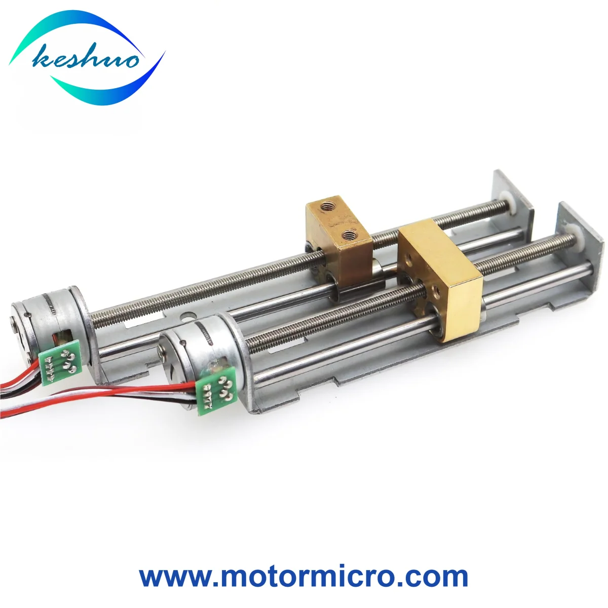
15BY25-77 15mm Stepper Linear Actuator, 9V, 62mm Stroke, Copper Slider

Description
15BY25-77 Lead Screw Stepper Linear Actuator
The 15BY25-77 is a miniature linear slide actuator manufactured by Keshuo Motor. It combines a 15 mm permanent magnet stepper motor, a lead screw mechanism, a linear guide rail and a copper slider to produce controlled linear movement.
The assembly operates with a nominal 9 V DC stepper motor and provides a listed effective travel of 62 mm. Its two-phase bipolar motor has an 18° step angle, allowing the slider to move incrementally along the lead screw when driven by a compatible stepper motor controller.
The copper slider travels along the guide mechanism as the lead screw rotates. Actual linear displacement per motor step depends on the lead screw pitch and driving method.
Main Technical Specifications
Model: 15BY25-77
Manufacturer: Keshuo Motor
Product Type: Lead Screw Stepper Linear Actuator
Motor Type: Permanent Magnet Stepper Motor
Motor Diameter: 15.0 mm
Motor Thickness: 13.0 mm
Rated Voltage: 9 V DC
Number of Phases: 2
Step Angle: 18° per step
Drive Mode: Bipolar
Effective Linear Stroke: 62 mm
Transmission: Lead Screw
Guide Mechanism: Linear Slide Rail
Slider Type: Copper Slider
Electrical Specifications
The following values are based on the supplied 15BY25-77 motor reference data.
Phase Resistance: 10 Ω ±10% at 25°C
Listed Current per Phase: 500 mA
Maximum Response Frequency: Greater than 1,300 PPS
Maximum Starting Frequency: Greater than 900 PPS
Coil Insulation Class: Class E
Dielectric Strength: 100 V AC for 1 second
Insulation Resistance: At least 50 MΩ at 500 V DC
Operating Temperature Range: -10°C to +55°C
Motor Surface Temperature: 80°C or lower
Listed Noise Level: ≤50 dB
The original performance information also reports a pull-out value greater than 230 g·cm at 125 PPS. Because g·cm is a torque unit rather than a linear force unit, this figure should not be interpreted as actuator thrust without further technical confirmation.
The listed voltage, winding resistance and phase current should be checked against the intended motor driver and excitation conditions. Noise and frequency specifications also depend on operating and test conditions.
Lead Screw and Copper Slider Assembly
The actuator uses a rotating lead screw to transfer motor rotation into linear displacement. The copper slider moves along the guide rail, providing a moving interface for a connected mechanism.
The 62 mm effective stroke represents the specified linear travel range, not the motor body length or the complete actuator assembly length.
Important mechanical considerations include:
Available installation length and mounting space
Effective travel required by the equipment
Lead screw pitch and linear movement per step
Slider attachment and load direction
Required axial force and operating speed
Motor drive current and operating duty cycle
Lead screw pitch, maximum axial thrust and positioning accuracy are not specified in the supplied reference data. These parameters should be confirmed before selecting the actuator for a particular load.
Applications
The 15BY25-77 actuator can be evaluated for compact linear positioning mechanisms in the following equipment:
Precision Instruments
Small adjustment assemblies requiring short-distance linear movement and controlled positioning.
Laboratory Equipment
Light-load positioning mechanisms used in testing fixtures, sample handling devices and compact laboratory instruments.
Small Automation Systems
Miniature linear slides for moving lightweight components between defined mechanical positions.
Robotics and Prototyping
Compact experimental motion assemblies and educational equipment using lead screw-driven linear movement.
Actual application suitability depends on the required axial load, stroke, operating speed, mounting arrangement and working conditions.
OEM Customization and Sample Orders
Keshuo Motor supports OEM projects involving miniature stepper motors and lead screw-driven linear motion assemblies.
Depending on the selected motor and slide design, customization may include motor winding specifications, shaft arrangements, lead screw configurations, wiring connections and mechanical interfaces.
For technical review or custom sample requests, please provide:
Required Supply Voltage
Effective Linear Stroke
Operating Speed
Axial Load or Required Thrust
Available Installation Dimensions
Mounting and Slider Connection Details
Operating Duty Cycle
Estimated Order Quantity
Availability: Currently out of stock. Production and sample availability should be confirmed before ordering.
Development Sample Lead Time: 10–15 working days, subject to configuration and manufacturing schedule.
Bulk order quotations are available upon request.
All listed specifications are reference values. Final electrical characteristics, mechanical drawings and operating performance should be confirmed before sample approval and volume production.