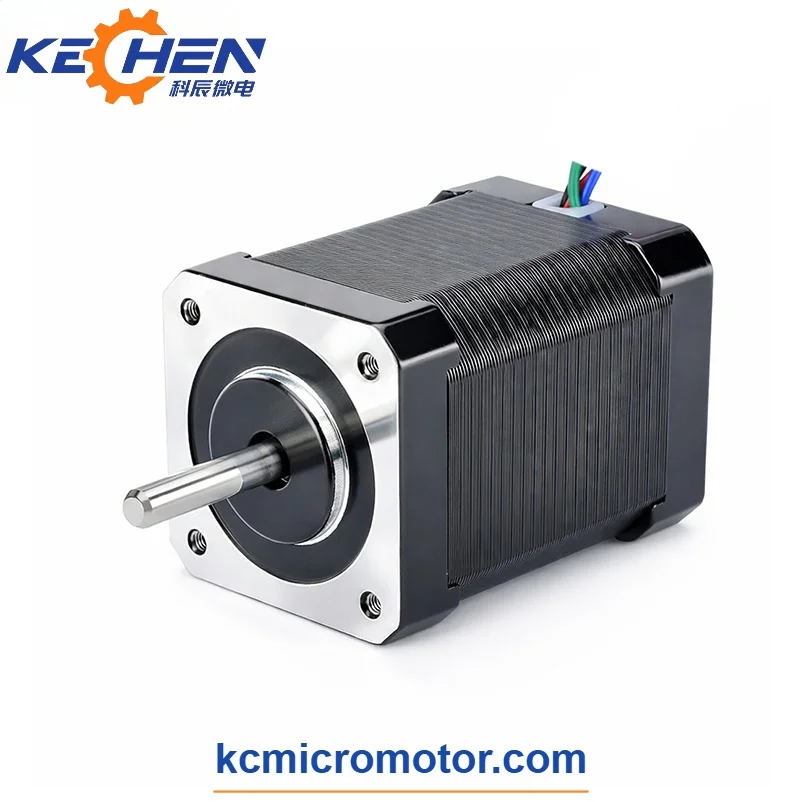
KC-42HYB60 NEMA 17 60mm Stepper Motor, 0.9°, 2A, D Shaft

Description
KC-42HYB60 NEMA 17 60mm Stepper Motor
The KC-42HYB60 is a two-phase NEMA 17 hybrid stepper motor manufactured by Kechen Motor. It features a 42.2 × 42.2 mm frame, a 60 mm motor body length and a 0.9° step angle for controlled rotary positioning.
With 400 full steps per revolution, this NEMA 17 0.9 degree stepper provides smaller native angular increments than a conventional 1.8° stepper motor. The reference configuration has a rated current of 2 A per phase and a holding torque of 6.7 kg·cm.
The motor uses a D-type output shaft and can be considered for precision positioning equipment, desktop CNC feed systems, 3D printer motion axes and compact automation mechanisms.
Main Technical Specifications
Model: KC-42HYB60
Manufacturer: Kechen Motor
Motor Type: Two-Phase Hybrid Stepper Motor
Frame Standard: NEMA 17
Frame Dimensions: 42.2 × 42.2 mm
Motor Body Length: 60 mm
Step Angle: 0.9° per step
Full Steps per Revolution: 400
Number of Phases: 2
Rated Current: 2 A per phase
Phase Resistance: 1.8 Ω
Phase Inductance: 5.2 mH
Holding Torque: 6.7 kg·cm
Reference Drive Supply Range: 3–24 V DC
Output Shaft: D-type
Mounting Hole Spacing: 31 ±0.1 mm
Mounting Holes: 4 × M3
Minimum Thread Depth: 4.0 mm
Front Pilot Diameter: Ø22 mm (+0 / -0.05 mm)
Shaft Diameter Options: Ø5 mm, Ø6.5 mm and Ø8 mm
The listed electrical and mechanical specifications refer to the KC-42HYB60 configuration. Final shaft dimensions and wiring arrangements should be confirmed against the selected motor drawing.
0.9 Degree Step Angle and Motion Control
The KC-42HYB60 provides a native step angle of 0.9°, corresponding to 400 full steps per revolution.
Compared with a conventional 1.8° NEMA 17 motor, which provides 200 full steps per revolution, the smaller step angle doubles the number of commanded full-step positions.
This characteristic can be useful in positioning systems requiring smaller angular increments before electronic microstepping is applied.
Actual positioning accuracy depends on the motor driver, mechanical load, shaft coupling, transmission backlash and control system.
For applications requiring finer motion, the NEMA 17 stepper motor 0.9 degree configuration should be evaluated together with the complete mechanical transmission.
Electrical Performance and Driver Selection
The KC-42HYB60 uses a winding configuration rated at 2 A per phase.
Electrical reference values include:
Rated Phase Current: 2 A
Phase Resistance: 1.8 Ω
Phase Inductance: 5.2 mH
Reference Driver Supply Range: 3–24 V DC
This NEMA 17 2A motor should be operated using a compatible current-regulated stepper driver.
The rated phase current must be distinguished from the driver supply voltage. Based on the listed winding resistance, the nominal resistive voltage at 2 A is approximately 3.6 V per phase.
A higher driver supply voltage must not be applied directly across the winding without suitable current regulation.
The selected driver should be evaluated according to current limits, required operating speed, acceleration, load inertia and motor temperature.
Holding Torque and Load Characteristics
The reference holding torque of the KC-42HYB60 is 6.7 kg·cm.
Holding torque describes the motor's static holding capability under specified energized conditions. It does not represent the available running torque at every operating speed.
When evaluating a high torque NEMA 17 stepper motor, engineers should consider:
Required Running Torque
Motor Operating Speed
Acceleration and Deceleration
Load Inertia
Shaft Coupling and Transmission
Operating Duty Cycle
Driver Current Settings
Available Cooling
For lead screw systems, pulley-driven axes and other mechanical transmissions, the motor must be matched to the actual working load.
NEMA 17 Motor Dimensions and D-Shaft Configuration
The KC-42HYB60 uses a nominal 42 mm frame with a 60 mm motor body length.
The mounting interface includes:
Frame Size: 42.2 × 42.2 mm
Mounting Hole Spacing: 31 ±0.1 mm
Mounting Thread: 4 × M3
Minimum Thread Depth: 4.0 mm
Front Pilot Diameter: Ø22 mm
The NEMA 17 D shaft motor configuration provides a flattened shaft surface for compatible couplings, pulleys and other mechanical connections.
Available shaft diameter options include 5 mm, 6.5 mm and 8 mm. D-shaft width, flat length and output shaft extension can be reviewed according to OEM requirements.
The final shaft length should be confirmed using the approved mechanical drawing.
For equipment integration, installation clearance should account for the 60 mm motor body, shaft extension, coupling dimensions and cable routing.
Applications
Precision Positioning Stages
The 0.9° step angle can support smaller commanded rotary increments in positioning mechanisms using suitable lead screws, couplings or other mechanical transmissions.
Desktop CNC Equipment
The motor can be considered for compact CNC feed systems and machine axes requiring a 42 mm frame motor. Running torque should be checked against the required feed speed and mechanical load.
3D Printer Motion Systems
Selected 3D printer motion axes may use the 60 mm NEMA 17 motor where the additional body length and electrical characteristics fit the machine design.
Automated Indexing Mechanisms
Compact rotary indexing equipment can use controlled step movement for repeated positioning between defined mechanical locations.
Laboratory Automation
Small positioning mechanisms in laboratory instruments and sample handling equipment may use a two-phase hybrid stepper motor with a compatible driver.
Dispensing and Inspection Equipment
Motor-driven adjustment mechanisms, inspection stages and dispensing assemblies may use this configuration when the required speed and load fall within the motor's operating capabilities.
Pick-and-Place Positioning Systems
The motor can be evaluated for selected positioning axes using belt drives, lead screws or other suitable transmissions.
Application suitability depends on the required motion profile, operating torque, driver configuration and mechanical installation.
NEMA 17 Series Configuration Options
Kechen Motor also supplies related NEMA 17 hybrid stepper motor configurations with different body lengths.
Reference motor body lengths include:
24 mm
28 mm
33 mm
40 mm
48 mm
60 mm
68 mm
The electrical characteristics and holding torque vary by model.
The KC-42HYB60 is a 60 mm body configuration with a 0.9° step angle and 2 A rated current. Other models in the series may use different winding specifications, step angles and shaft arrangements.
Motor selection should consider installation space, required torque, operating speed and driver compatibility.
OEM Stepper Motor Customization
Kechen Motor supports OEM and ODM manufacturing of NEMA 17 hybrid stepper motors for industrial and equipment integration projects.
Depending on the selected design, customization options may include:
Rated Phase Current
Winding Resistance
Holding Torque Requirements
Shaft Diameter
Output Shaft Length
D-Shaft Flat Dimensions
Lead Wires and Connectors
Mechanical Installation Requirements
For custom motor projects, customers should provide the required phase current, operating speed, load torque, installation dimensions, output shaft specifications and estimated order quantity.
Sample Development and Ordering
Product Model: KC-42HYB60
Motor Type: NEMA 17 Hybrid Stepper Motor
Motor Body Length: 60 mm
Step Angle: 0.9°
Rated Current: 2 A per phase
Holding Torque: 6.7 kg·cm
Custom Sample Lead Time: 10–20 days, subject to technical specifications and production scheduling.
Bulk order quotations are available based on the required configuration and order quantity.
For sample evaluation or production inquiries, please provide:
Required Motor Specifications
Stepper Driver and Supply Voltage
Operating Speed and Load Torque
Shaft Dimensions
Mounting and Installation Requirements
Operating Duty Cycle
Estimated Order Quantity
All listed specifications are reference values. Final winding characteristics, mechanical drawings and operating performance should be confirmed before sample approval and volume production.